|
|
Post by moflint on Mar 1, 2017 21:30:21 GMT 7
Dual stingo - first test.... At full power I am drawing 1.5 amps from 2 x 12v 7ah source. I am charging 2 x 12v 7ah in parallel to see how long it will take and efficiency. Coils - DC resistance of 1 ohm, "singing", getting warm - 100 deg F. in cool room (56 deg F). Transistors (TIP41 and TIP42 series) run at 70 deg F with small heatsink fan on which is run from source batt. Will post results of this test tomorrow. |
|
|
|
Post by gaslan on Mar 3, 2017 4:33:25 GMT 7
Ok. I am curious on how you add the capacitor. The purpose of the input capacitor is to act as high current provider since battery or solar panel may not be able to supply as much.
I think TV transformer have rectified secondary. The rectifier will reduce high voltage output.
-----------------------------------------------------------------------------------
Two electrolytic capacitors let the wheel running when connected to the solar panel.
The connection was: positive wire from solar panel to positive pole of the capacitors in parallel.
Negative wire from panel to negative pole of the capacitors.
From condensers to the electronic board.
The transformer in the pic has a fuse and a condenser on a small board.
I don’t know the voltage peak from my stingo.
|
|
|
|
Post by moflint on Mar 3, 2017 22:07:06 GMT 7
I have been testing my first dual stingo build. Very interesting circuit!
There seems to be lots of factors that effect performance, such as touching wires and pots - even having wires higher up or closer to others.
Charging seems good, but the condition of my batteries (whether they respond well to radiant or not) is an unknown factor right now.
Here is a short video to show the effect of adding magnets at 90 degrees to the toroid coils:
|
|
|
|
Post by Sucahyo on Mar 4, 2017 8:18:48 GMT 7
Ok. I am curious on how you add the capacitor. The purpose of the input capacitor is to act as high current provider since battery or solar panel may not be able to supply as much. I think TV transformer have rectified secondary. The rectifier will reduce high voltage output. ----------------------------------------------------------------------------------- Two electrolytic capacitors let the wheel running when connected to the solar panel. The connection was: positive wire from solar panel to positive pole of the capacitors in parallel. Negative wire from panel to negative pole of the capacitors. From condensers to the electronic board. The transformer in the pic has a fuse and a condenser on a small board. I don’t know the voltage peak from my stingo. Thanks. What is the capacitor value again? sorry I don't remember the value. Have you ever try to use smaller capacitor? I wonder if we can use voltage stabilizer / bypass capacitor trick: 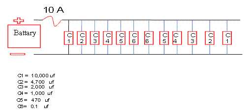 |
|
|
|
Post by Sucahyo on Mar 4, 2017 8:21:26 GMT 7
Dual stingo - first test.... At full power I am drawing 1.5 amps from 2 x 12v 7ah source. I am charging 2 x 12v 7ah in parallel to see how long it will take and efficiency. Coils - DC resistance of 1 ohm, "singing", getting warm - 100 deg F. in cool room (56 deg F). Transistors (TIP41 and TIP42 series) run at 70 deg F with small heatsink fan on which is run from source batt. Will post results of this test tomorrow. That is great result. Thanks for sharing. Is that 12V source or 24V ? 12V in paralel? I think you need to measure the output current too. |
|
|
|
Post by Sucahyo on Mar 4, 2017 8:33:38 GMT 7
I have been testing my first dual stingo build. Very interesting circuit! There seems to be lots of factors that effect performance, such as touching wires and pots - even having wires higher up or closer to others. Charging seems good, but the condition of my batteries (whether they respond well to radiant or not) is an unknown factor right now. Here is a short video to show the effect of adding magnets at 90 degrees to the toroid coils: Thanks for the video  . New battery will be reconditioned, and usually have their capacity increase, even the source battery. Make sure to avoid over discharge (11.5V) or overcharge (the battery start to get hot). It is interesting that adding magnet change the consumption. That remind me of magnetic amplifier, to use DC current to control the output of a transformer.  Yes, touching stingo can change power too. I think stingo is a good method to harvest energy from the atmosphere and earth. We can directly use antenna and 50 liter of water to increase the power of stingo.   Yes, if you want to run the circuit 24/7, you may need to add fan to the coil too. But I wonder why your circuit only draw 400mA at maximum power, with two stingo? |
|
|
|
Post by gaslan on Mar 5, 2017 18:35:17 GMT 7
Charger monocoil.doc (97 KB) Here is the stingo scheme I'm using so we better understand what I'm experimenting on. The capacitor is 1 uF 630 V and transistors are BD241C and BD242C other components are the same as in drawing. The input is about 400 ma ( with a 2a 12 v transformer ) output changes according to coil used: ignition col give an input ( to charged battery ) of 50 ma todoid 45mm diameter 1 wire an input of 250 ma I use an analogic amperometer 1 a DC I cannot measure peaks or I don't see them.
I mounted the stingo on a ventronite. ___________________________ Yes, touching stingo can change power too. I think stingo is a good method to harvest energy from the atmosphere and earth. We can directly use antenna and 50 liter of water to increase the power of stingo.
Touching with my fingers negative or positive wires no change seen in the amperometer. I put a single copper wire of 1 mm diameter in a underground chamber with 11.000 lt of water and touched with the other end the stingo, on positive or negative wires, on the coil end any possible naked wire, but no change seen in the amperometer. I put a strong neodymium (about 70 kg force ) on toroid and around stingo but no electrical change seen. I connected the amperometer between transformer and stingo just right now. The strange thing is that I always mesured 400/450 mA max, well at first went over 1 amp and now abou 900 mA, but the input to battery haven't changed . ____________________________________ What is the capacitor value again? sorry I don't remember the value. Have you ever try to use smaller capacitor?
I wonder if we can use voltage stabilizer / bypass capacitor trick:
Each capacitor has 10.000 uF 63 VDC, no I didn't try smaller one. I thought the same but trying a voltage regulator. Did you try assemblying the scheme of harvesting energy from earth and from athmosphere ? diode must be 20 Kv ? the capacitor of 20 kv the 0.001 mfd stand for 0.001 uF ? thank you. Diode and cap must have same kv ?
|
|
|
|
Post by moflint on Mar 5, 2017 21:30:05 GMT 7
Thank you for the atmosphere-to-ground circuit Sucahyo - looks simple in theory - is that an "electret" system? When my battery charging stingo is tuned I would like to try some of these other circuits... lots of potential for experiments :-)
Regarding the amp draw - my meter has two scales, 5a and 1a - it was actually drawing 2a which was on the top scale, not 400mM from the bottom scale. This was with N42 magnets which boosted the power by about 25%.
I am not sure how to test the output amps. Do I put an ammeter between the positive output from the capacitor to the charging battery? I thought the HV spikes might break my meter.
I have been attempting to run the dual stingo at 24v. Battery charging is great. I am doing a Bedini/Friedrich 24v (2 x 12v = 24v) to 12v (2 x 12v = 12v) "split positive" arrangement to recycle the battery power, but I always blow the diode that is in parallel with the 47k resistor. My diodes are rated at 1000v so I am guessing that the voltage spikes from the coil are destroying the diodes (?). I am trying to find a high voltage (1800v or 2500v) diode to test properly.
|
|
|
|
Post by moflint on Mar 5, 2017 21:48:28 GMT 7
I put a strong neodymium (about 70 kg force ) on toroid and around stingo but no electrical change seen. I tried this with dual (two coils) stingo. I used 40mm dia x 8mm thick x 5mm ferrite magnet - 15kg pull. When I put 2 of these under the first coil - at 90 degrees - ie, thin edge of the toroid on top of magnet - the circuit amp draw went down from ~1750mA to ~1500mA. Then I added same magnets under second coil and the circuit amp draw went up from ~1500mA to ~2000mA. So one coil with magnets = less then circuit with no magnets, but two coils with magnets = more than circuit with no magnets. |
|
|
|
Post by Sucahyo on Mar 8, 2017 12:03:32 GMT 7
Here is the stingo scheme I'm using so we better understand what I'm experimenting on. The capacitor is 1 uF 630 V and transistors are BD241C and BD242C other components are the same as in drawing. The input is about 400 ma ( with a 2a 12 v transformer ) output changes according to coil used: ignition col give an input ( to charged battery ) of 50 ma todoid 45mm diameter 1 wire an input of 250 ma I use an analogic amperometer 1 a DC I cannot measure peaks or I don't see them.
I mounted the stingo on a ventronite. ___________________________ Yes, touching stingo can change power too. I think stingo is a good method to harvest energy from the atmosphere and earth. We can directly use antenna and 50 liter of water to increase the power of stingo.
Touching with my fingers negative or positive wires no change seen in the amperometer. I put a single copper wire of 1 mm diameter in a underground chamber with 11.000 lt of water and touched with the other end the stingo, on positive or negative wires, on the coil end any possible naked wire, but no change seen in the amperometer. I put a strong neodymium (about 70 kg force ) on toroid and around stingo but no electrical change seen. I connected the amperometer between transformer and stingo just right now. The strange thing is that I always mesured 400/450 mA max, well at first went over 1 amp and now abou 900 mA, but the input to battery haven't changed . ____________________________________ What is the capacitor value again? sorry I don't remember the value. Have you ever try to use smaller capacitor?
I wonder if we can use voltage stabilizer / bypass capacitor trick:
Each capacitor has 10.000 uF 63 VDC, no I didn't try smaller one. I thought the same but trying a voltage regulator. Did you try assemblying the scheme of harvesting energy from earth and from athmosphere ? diode must be 20 Kv ? the capacitor of 20 kv the 0.001 mfd stand for 0.001 uF ? thank you. Diode and cap must have same kv ? Thanks for the diagram. I think that explain the difference. The main difference is in the diode. Unlike other radiant charger Stingo output do not use FWBD. The reason why stingo do not use normal full wave bridge diode is because in stingo only the negative spike need the capacitor. The forward spike must not be blocked by capacitor. So the current from coil to charged battery is unblocked, the current from source to charged battery is blocked by capacitor, so it will only allow a brief pulse of current. If the forward spike is blocked by capacitor too, then the output will be significantly lower. The reason why that capacitor need to be high voltage is because stingo can produce voltage exceeding 1000V. I think you should lower the R2 value to 37k ohm. Replace VR1 with 50K resistor. Also please read this: freeenergyindonesia.proboards.com/thread/74/baterai-rusak-karena-listrik-radiantThe water must not be grounded. Must not connect to the earth ground. for example. 3V stingo will produce about 75V on analog meter. With earth ground it will raise to 80V. With body or 50 liter of water in a plastic container will raise it to 150V. Almost The same increase if I attach some long wire The ground effect seems to work best at low power. I never try to actually use energy harvesting during real charging. Which diode / capacitor with 20kv? If it is for voltage stabilizer, then twice source voltage (25V). |
|
|
|
Post by Sucahyo on Mar 8, 2017 12:11:26 GMT 7
Thank you for the atmosphere-to-ground circuit Sucahyo - looks simple in theory - is that an "electret" system? When my battery charging stingo is tuned I would like to try some of these other circuits... lots of potential for experiments :-)Regarding the amp draw - my meter has two scales, 5a and 1a - it was actually drawing 2a which was on the top scale, not 400mM from the bottom scale. This was with N42 magnets which boosted the power by about 25%.
I am not sure how to test the output amps. Do I put an ammeter between the positive output from the capacitor to the charging battery? I thought the HV spikes might break my meter. I have been attempting to run the dual stingo at 24v. Battery charging is great. I am doing a Bedini/Friedrich 24v (2 x 12v = 24v) to 12v (2 x 12v = 12v) "split positive" arrangement to recycle the battery power, but I always blow the diode that is in parallel with the 47k resistor. My diodes are rated at 1000v so I am guessing that the voltage spikes from the coil are destroying the diodes (?). I am trying to find a high voltage (1800v or 2500v) diode to test properly.
Thanks. Yes, similar to electret but we get actual gain. Maybe work better with much smaller power level. I wonder how low stingo can run. Ok. 2A is normal. But I wonder how magnet change the output power. I wonder if it only increase consumption without increasing the output. put the amp meter between the positive output and the battery. It would be fine if you connect it when the stingo is off. Do not connect it when stingo is still on. Make sure the connection is secure / not loose. I never run 24V system long enough, it is interesting that the diode is the one that blows. try with higher current rating too. |
|
|
|
Post by Sucahyo on Mar 8, 2017 12:15:17 GMT 7
I put a strong neodymium (about 70 kg force ) on toroid and around stingo but no electrical change seen. I tried this with dual (two coils) stingo. I used 40mm dia x 8mm thick x 5mm ferrite magnet - 15kg pull. When I put 2 of these under the first coil - at 90 degrees - ie, thin edge of the toroid on top of magnet - the circuit amp draw went down from ~1750mA to ~1500mA. Then I added same magnets under second coil and the circuit amp draw went up from ~1500mA to ~2000mA. So one coil with magnets = less then circuit with no magnets, but two coils with magnets = more than circuit with no magnets. Interesting |
|
|
|
Post by moflint on Mar 8, 2017 22:04:18 GMT 7
I have made a short video to show the difference of input amps and output amps, with, and without magnets under the coils of dual stingo.
The results were:
WITHOUT magnets:
input 1500mA, output 470mA
WITH magnets
input 2000mA, output 720mA
NOTE - before I started testing with magnets today - before any magnetic influence, my initial input/output readings were:
input 1350mA, output 490mA
This is in contrast to my later test WITHOUT magnets resulting in 1500mA input and 470mA output (approx 10 mins after testing WITH magnets). Therefore it seems like the magnetic field influences the coils for some time AFTER the magnets are removed.
I will now continue to test at 24v and will post my results in the next few days.
|
|
|
|
Post by moflint on Mar 8, 2017 22:52:25 GMT 7
Thank you for the atmosphere-to-ground circuit Sucahyo - looks simple in theory - is that an "electret" system? When my battery charging stingo is tuned I would like to try some of these other circuits... lots of potential for experiments :-)Regarding the amp draw - my meter has two scales, 5a and 1a - it was actually drawing 2a which was on the top scale, not 400mM from the bottom scale. This was with N42 magnets which boosted the power by about 25%.
I am not sure how to test the output amps. Do I put an ammeter between the positive output from the capacitor to the charging battery? I thought the HV spikes might break my meter. I have been attempting to run the dual stingo at 24v. Battery charging is great. I am doing a Bedini/Friedrich 24v (2 x 12v = 24v) to 12v (2 x 12v = 12v) "split positive" arrangement to recycle the battery power, but I always blow the diode that is in parallel with the 47k resistor. My diodes are rated at 1000v so I am guessing that the voltage spikes from the coil are destroying the diodes (?). I am trying to find a high voltage (1800v or 2500v) diode to test properly.
Thanks. Yes, similar to electret but we get actual gain. Maybe work better with much smaller power level. I wonder how low stingo can run. Ok. 2A is normal. But I wonder how magnet change the output power. I wonder if it only increase consumption without increasing the output. put the amp meter between the positive output and the battery. It would be fine if you connect it when the stingo is off. Do not connect it when stingo is still on. Make sure the connection is secure / not loose. I never run 24V system long enough, it is interesting that the diode is the one that blows. try with higher current rating too. Sucahyo, can a gain be found in stingo if we add a spark gap + earth (or water) connection to the circuit? I'm not sure how to do this because, at the moment, half of the flyback spike is going directly to the battery and half goes to the capacitor. Therefore the circuit would have to be changed quite a lot to achieve a spark gap and also keep the "half bridge" arrangement. I am a novice and this is would take me a long time to figure it out! Regarding the atmosphere-to-ground circuit you posted - are you just showing a principle here, so 1000 foot wire + spark gap/ignition coil + earth is like antenna + stingo + water "ground", or are you saying the stingo circuit can drive the ignition coil in this circuit? Also the other circuit (with blue capacitor) - is that to show the principle, or can that use stingo? Thank you. |
|
|
|
Post by Sucahyo on Mar 9, 2017 8:42:32 GMT 7
I have made a short video to show the difference of input amps and output amps, with, and without magnets under the coils of dual stingo. The results were: WITHOUT magnets: input 1500mA, output 470mA WITH magnets input 2000mA, output 720mA NOTE - before I started testing with magnets today - before any magnetic influence, my initial input/output readings were: input 1350mA, output 490mAThis is in contrast to my later test WITHOUT magnets resulting in 1500mA input and 470mA output (approx 10 mins after testing WITH magnets). Therefore it seems like the magnetic field influences the coils for some time AFTER the magnets are removed. I will now continue to test at 24v and will post my results in the next few days.Thanks for the video. Thanks for testing. very interesting. I wonder why the result is unpredictable. Also why the there is left over of magnetic field. Have you ever try to change the magnet position? Maybe by placing magnet at the both side of the toroid, so the magnet cover both toroid hole? |
|
|
|
Post by Sucahyo on Mar 9, 2017 9:06:44 GMT 7
Sucahyo, can a gain be found in stingo if we add a spark gap + earth (or water) connection to the circuit? I'm not sure how to do this because, at the moment, half of the flyback spike is going directly to the battery and half goes to the capacitor. Therefore the circuit would have to be changed quite a lot to achieve a spark gap and also keep the "half bridge" arrangement. I am a novice and this is would take me a long time to figure it out! Regarding the atmosphere-to-ground circuit you posted - are you just showing a principle here, so 1000 foot wire + spark gap/ignition coil + earth is like antenna + stingo + water "ground", or are you saying the stingo circuit can drive the ignition coil in this circuit? Also the other circuit (with blue capacitor) - is that to show the principle, or can that use stingo? Thank you. I think stingo do not need spark gap. We can just use the antenna and the water as it is. I think the gain with this kind of connection already greater than from what people get from sparkgap & electret. An increase of 0.01 amp of charging voltage from the initial 0.1 amp is already decent for me. What do you mean by half flyback go to the battery half to the capacitor? I think all the forward spike go to the battery, and the backward spike are used to self oscillate stingo. Stingo have much smaller back spike than other radiant charger IIRC. For the most efficient output, actually single diode is better. But, this will ruin the battery. Which is the reason why I use strange bridge diode. Please read this thread, most content is in english: freeenergyindonesia.proboards.com/thread/74/baterai-rusak-karena-listrik-radiantUnless you have space, do not try to experiment with stingo spark. Especially if you use single wire coil. Even tesla have stand far away from his spark disrupter. I post the diagram to show the existing method to generate power. atmosphere and earth have power, the problem is it is in a very high frequency, or very high high voltage with very very small amp. So, there is a need for step down transformer. I think that spark gap is being used to step down the voltage to a useable range. The spark will allow current to flow. In a small scale spark said to be produced twice a day or so, but I imagine tesla may have continuous spark. The spark it self waste power. With stingo, the energy is already useable. we can already get power boost without the spark. The water must be isolated from the ground. I think the ground is no longer negative because power company use it as grounding. |
|
|
|
Post by gaslan on Mar 10, 2017 3:58:13 GMT 7
I put a strong neodymium (about 70 kg force ) on toroid and around stingo but no electrical change seen. I tried this with dual (two coils) stingo. I used 40mm dia x 8mm thick x 5mm ferrite magnet - 15kg pull. When I put 2 of these under the first coil - at 90 degrees - ie, thin edge of the toroid on top of magnet - the circuit amp draw went down from ~1750mA to ~1500mA. Then I added same magnets under second coil and the circuit amp draw went up from ~1500mA to ~2000mA. So one coil with magnets = less then circuit with no magnets, but two coils with magnets = more than circuit with no magnets. I tried again finger touching or magnet ( 3/5 Kg ) on toroid but my stingo stands still. As far as I've seen, the assembling of an electronic circuit make performance change, whether you make a compact ventronite board, or a bread board or you connect the components with wires. As you read above, a magnet around stingo make, irreversible ? it suck more current from the source. |
|
|
|
Post by gaslan on Mar 10, 2017 4:42:37 GMT 7
Thanks for the diagram. I think that explain the difference. The main difference is in the diode. Unlike other radiant charger Stingo output do not use FWBD. The reason why stingo do not use normal full wave bridge diode is because in stingo only the negative spike need the capacitor. The forward spike must not be blocked by capacitor. So the current from coil to charged battery is unblocked, the current from source to charged battery is blocked by capacitor, so it will only allow a brief pulse of current. If the forward spike is blocked by capacitor too, then the output will be significantly lower. The reason why that capacitor need to be high voltage is because stingo can produce voltage exceeding 1000V. I think you should lower the R2 value to 37k ohm. Replace VR1 with 50K resistor. Thank you I'll try itAlso please read this: freeenergyindonesia.proboards.com/thread/74/baterai-rusak-karena-listrik-radiantThe water must not be grounded. Must not connect to the earth ground. I put a single copper wire, diameter mm. 0,60 500 mm long in a plastic container ( 300 lt) and touched with one end the stingo ( negative wire, toroid connection, positive wire, but nothing, the amperometer doesn't move, as explained above, the reason as far as I can know, could be the board assembling.for example. 3V stingo will produce about 75V on analog meter. With earth ground it will raise to 80V. With body or 50 liter of water in a plastic container will raise it to 150V. Almost The same increase if I attach some long wire The ground effect seems to work best at low power. I never try to actually use energy harvesting during real charging. Which diode / capacitor with 20kv? If it is for voltage stabilizer, then twice source voltage (25V). I made a mistake assembling the board, it has been working since now anyway, but now the differences are :
The 12 v 2 Amp transformer let the transistor BD241c get hotter than before.
I changed it and used a multivoltage From 1,5 to 12 v 1 Amp transformer.
I started with 1,5 V up to 12 V position where stingo charges a bit.
Tuning VR2 ( I kept on 0 before ) by rising resistance, rise the output amperage and input tension from 4 v rise to 10 v ( max tension I can have ) the transistor is cold but I just made a try for a minute charging a battery, later with the 2 Amp transformer the transistor was too hot and got stuck.
The input current I cannot measure because the amperometer is 1 Amp and I reached the top measurable current.
As you said, in a single toroid stingo 1 Amp input should be a safe level of current.
If I have a source of 3 Amp I should make a 3 toroid Stingo so I don't thermically stress the transistor. Is it correct ?
|
|
|
|
Post by Sucahyo on Mar 10, 2017 10:20:45 GMT 7
I put a single copper wire, diameter mm. 0,60 500 mm long in a plastic container ( 300 lt) and touched with one end the stingo ( negative wire, toroid connection, positive wire, but nothing, the amperometer doesn't move, as explained above, the reason as far as I can know, could be the board assembling.I made a mistake assembling the board, it has been working since now anyway, but now the differences are :
The 12 v 2 Amp transformer let the transistor BD241c get hotter than before.
I changed it and used a multivoltage From 1,5 to 12 v 1 Amp transformer.
I started with 1,5 V up to 12 V position where stingo charges a bit.
Tuning VR2 ( I kept on 0 before ) by rising resistance, rise the output amperage and input tension from 4 v rise to 10 v ( max tension I can have ) the transistor is cold but I just made a try for a minute charging a battery, later with the 2 Amp transformer the transistor was too hot and got stuck.
The input current I cannot measure because the amperometer is 1 Amp and I reached the top measurable current.
As you said, in a single toroid stingo 1 Amp input should be a safe level of current.
If I have a source of 3 Amp I should make a 3 toroid Stingo so I don't thermically stress the transistor. Is it correct ?
Ok, maybe you should try grounding/aerial after correcting the stingo. The PNP should be cold and the NPN should be very very hot when running. 1 amp is the limit to prevent destroying the transistor. The NPN will die in second if run without load. 3 amp may be not enough for 1 amp stingo. But you will get more efficient output if you use it for more than 1 stingo. But I think you may not be able to reach 3 amp consumption even with 3 stingo. |
|
|
|
Post by moflint on Mar 10, 2017 18:46:07 GMT 7
I am sorry - I do not really understand how the circuit works because I'm new to electronics and still learning the basics. I thought that half of the negative spike went directly to the battery, but also half is absorbed by the capacitor and discharge back to the battery as a positive charge(?)
This was a mistake. My diode is not blowing, but It seems like it is! When I check the diode with a multimeter (in diode check mode) it shows the voltage - 0.540v one way, 0.720v the other, across both polarities indicating that the diode is not functioning correctly. However it now seems this effect is caused by the coil. Remove the coil and the diode checks out fine. This happens after the circuit has been running. If the circuit has not been running for several hours this does not happen. Strange.
I have tried the magnets in every configuration. The most power increase is achieved by using magnets at 90 degrees to the toroid. Here are some more test results with magnets. (Exactly same input source - 12.2v 4a power supply. Only change is adding magnets.)
700mA in, 210mA out, 30% efficiency (single stingo, no magnets)
1380mA in, 420mA out, 30% efficiency (dual stingo, no magnets)
1270mA in, 470mA out, 37% efficiency (dual stingo, coil 1 with 1 magnet, coil 2 with 0 magnet) *
1380mA in, 520mA out, 38% efficiency (dual stingo, coil 1 with 5 magnets, coil 2 with 0) **
2300mA in, 840mA out, 36% efficiency (dual stingo, coil 1 with 5 magnets, coil 2 with 1 magnet)
2570mA in, 920mA out, 36% efficiency (dual stingo, coil 1 with 5 magnets, coil 2 with 5)
* This is very interesting result with just one magnet under one coil - input amps dropped while output amps increased!
** NB, extra 100mA output for no extra input
I think my stingo circuit is not as efficient as possible. It takes input of about 700 mA to output 210mA. I was hoping for about 50% efficiency. This is more like 30% and seems a bit poor.
Also the dual stingo (2 coils) does not seem synergistic in my case. Dual coil input 1380mA, output 420mA = 30% efficient, same as my single stingo.
|
|


 .
.

