|
|
Post by moflint on Mar 10, 2017 18:51:16 GMT 7
Where is the best place in the stingo circuit to connect antenna, and also the water connection? Thank you.
Yes, any gain is a great result :-)
|
|
|
|
Post by Sucahyo on Mar 12, 2017 13:32:23 GMT 7
I am sorry - I do not really understand how the circuit works because I'm new to electronics and still learning the basics. I thought that half of the negative spike went directly to the battery, but also half is absorbed by the capacitor and discharge back to the battery as a positive charge(?) The current that goes to the capacitor prevented by diode. Capacitor is being used to allow only momentary current from the source positive. I don't think switching the diode and capacitor position will change anything. But you maybe correct that only half of the spike goes to the battery. Stingo output with 4 diode and 1 capacitor has half the efficiency of stingo output with one diode. But this also means that the current that goes to the capacitor do not charge the battery. I think the battery get normal electricity charging not from the capacitor, but from source positive that flow because of reverse coil spike. I think when the current from the coil is terminated, the current will flow forward and backward in diminishing way. But the second flow is much weaker than the first one.   This was a mistake. My diode is not blowing, but It seems like it is! When I check the diode with a multimeter (in diode check mode) it shows the voltage - 0.540v one way, 0.720v the other, across both polarities indicating that the diode is not functioning correctly. However it now seems this effect is caused by the coil. Remove the coil and the diode checks out fine. This happens after the circuit has been running. If the circuit has not been running for several hours this does not happen. Strange. Interesting. Please check if the diode is capable of correctly block source voltage. Use the diode in series with the probe ans use it to measure battery voltage. Check forward and backward reading. I have tried the magnets in every configuration. The most power increase is achieved by using magnets at 90 degrees to the toroid. Here are some more test results with magnets. (Exactly same input source - 12.2v 4a power supply. Only change is adding magnets.) 700mA in, 210mA out, 30% efficiency (single stingo, no magnets) 1380mA in, 420mA out, 30% efficiency (dual stingo, no magnets) 1270mA in, 470mA out, 37% efficiency (dual stingo, coil 1 with 1 magnet, coil 2 with 0 magnet) * 1380mA in, 520mA out, 38% efficiency (dual stingo, coil 1 with 5 magnets, coil 2 with 0) ** 2300mA in, 840mA out, 36% efficiency (dual stingo, coil 1 with 5 magnets, coil 2 with 1 magnet) 2570mA in, 920mA out, 36% efficiency (dual stingo, coil 1 with 5 magnets, coil 2 with 5) * This is very interesting result with just one magnet under one coil - input amps dropped while output amps increased! ** NB, extra 100mA output for no extra input Thanks for testing. very interesting. I wonder if more efficiency with one magnet only happen because this make the stingo run at different speed so both do not consume current at the same time. I think my stingo circuit is not as efficient as possible. It takes input of about 700 mA to output 210mA. I was hoping for about 50% efficiency. This is more like 30% and seems a bit poor. Also the dual stingo (2 coils) does not seem synergistic in my case. Dual coil input 1380mA, output 420mA = 30% efficient, same as my single stingo. I think 30% is not 30% efficiency. You need to compare it with commercial charger. See how fast the the battery filled with the same input current. The efficiency of my stingo is about the same but can charge 6 times faster than commercial charger. Stingo also twice more efficient than joule thief. This is the reason why I want to drive the transistor directly with the spike. Unfortunately I still do not have time for this. I think your single stingo will not have the same efficiency if you force it to run at the same current consumption. Try to compare it with the same input current. |
|
|
|
Post by Sucahyo on Mar 12, 2017 13:39:44 GMT 7
Where is the best place in the stingo circuit to connect antenna, and also the water connection? Thank you. Yes, any gain is a great result :-) Yes  . When I test it, it does not matter if I connect the aerial or ground to the positive or the negative of the output. But for the health of the charged battery, I think we should connect the aerial to the side of the coil that is connected to the transistor. The ground would connect to the side of the coil that connected to the source positive. BTW, have you ever measure the output voltage against the ground? Different radiant circuit will produce different reaction. |
|
|
|
Post by moflint on Mar 14, 2017 5:51:19 GMT 7
I think when the current from the coil is terminated, the current will flow forward and backward in diminishing way. But the second flow is much weaker than the first one. Do you mean forwards = positive volts, backwards = negative volts? Please check if the diode is capable of correctly block source voltage. Use the diode in series with the probe ans use it to measure battery voltage. Check forward and backward reading. I have 11.4v in front of the diode and 7.3v behind it, when the circuit is running. My diode tester says the diode is broken so I replace the diode. Same thing happens with new diode. I remove the coil and re-test the diode and it's fine. I test the "dead" diodes that I replaced - they are all fine. Only when in contact with the coil does this behaviour happen. Sorry - this is my lack of experience with electronics I think. I wonder if more efficiency with one magnet only happen because this make the stingo run at different speed so both do not consume current at the same time. I could be. If I add a bit more resistance through the pot I can find a couple of spots that seem like better "resonance" - the output leaps - (but more draw on source) - but yet more resistance dialled into the pot. I think 30% is not 30% efficiency. You need to compare it with commercial charger. See how fast the the battery filled with the same input current. The efficiency of my stingo is about the same but can charge 6 times faster than commercial charger. Stingo also twice more efficient than joule thief. Yes for sure. I did not mean overall efficiency of charge going into battery, but simple amp reading. I saw a video of a stingo circuit that was input of 39mA and output of 19mA = 48.7% ratio. So I was aiming at similar ratio. I now have it at just over 40% output vs. input. BTW, have you ever measure the output voltage against the ground? Different radiant circuit will produce different reaction. I have not done this, but will try hopefully this week. Thank you, I will continue to test... |
|
|
|
Post by Sucahyo on Mar 14, 2017 9:33:59 GMT 7
Do you mean forwards = positive volts, backwards = negative volts? Forward = current that flow the same direction as when the coil receive current from power source. I have 11.4v in front of the diode and 7.3v behind it, when the circuit is running. My diode tester says the diode is broken so I replace the diode. Same thing happens with new diode. I remove the coil and re-test the diode and it's fine. I test the "dead" diodes that I replaced - they are all fine. Only when in contact with the coil does this behaviour happen. Sorry - this is my lack of experience with electronics I think. I think I experience something like that too. After that, I do not check the diode with multimeter diode mode. I check the diode with volt meter when connecting to battery. Surprisingly, some diode can not block battery voltage even if it is in a new condition. We need diode that can block battery voltage. So we can not rely on multimeter diode check mode. I could be. If I add a bit more resistance through the pot I can find a couple of spots that seem like better "resonance" - the output leaps - (but more draw on source) - but yet more resistance dialled into the pot. I see. interesting. Yes for sure. I did not mean overall efficiency of charge going into battery, but simple amp reading. I saw a video of a stingo circuit that was input of 39mA and output of 19mA = 48.7% ratio. So I was aiming at similar ratio. I now have it at just over 40% output vs. input. Ok. I think the choice of transistor, the power level, and charged battery internal resistance play a big part in the efficiency. Transistor with high amp capability usually are less efficient. More input power usually resulted in less efficiency. Low load resistance increase stingo efficiency. For maximum efficiency, you should replace all resistor with variable resistor. Different coil/transistor/charged battery need different resistor value for best efficiency. I have not done this, but will try hopefully this week. Thank you, I will continue to test... Thanks for sharing . |
|
|
|
Post by moflint on Mar 20, 2017 19:22:05 GMT 7
I think I experience something like that too. After that, I do not check the diode with multimeter diode mode. I check the diode with volt meter when connecting to battery. Surprisingly, some diode can not block battery voltage even if it is in a new condition. We need diode that can block battery voltage. So we can not rely on multimeter diode check mode. I have taken voltages (against negative of source battery) for my dual stingo circuit while drawing 1.83 amps at 12.2v, and outputting 750mA. I was using a single magnet under the second toroid coil to boost the circuit, and tuning the pot on the first coil to find best input/output ratio. The pot on the 2nd coil was fully open allowing full flow through the pot. Please see attached image. As you can see on the 1st coil I have 7.5v before the diode that is parallel with the 47K resistor, and 11.4v after the diode. On the second coil I have 5.8v before the diode and 10.4v after it. Do these readings, before and after the diode, seem good to you? Thank you.  |
|
|
|
Post by Sucahyo on Mar 21, 2017 9:48:39 GMT 7
I have taken voltages (against negative of source battery) for my dual stingo circuit while drawing 1.83 amps at 12.2v, and outputting 750mA. I was using a single magnet under the second toroid coil to boost the circuit, and tuning the pot on the first coil to find best input/output ratio. The pot on the 2nd coil was fully open allowing full flow through the pot. Please see attached image. As you can see on the 1st coil I have 7.5v before the diode that is parallel with the 47K resistor, and 11.4v after the diode. On the second coil I have 5.8v before the diode and 10.4v after it. Do these readings, before and after the diode, seem good to you? Thank you. That is great result . That is a great measurement. Thanks for that. It show a lot information. I am interested in the 26.3V reading on the capacitor. I wonder if we can somehow connect the charged battery negative to the source negative when the transistor is off. I wonder if we can safely remove the diode before the capacitor. What I mean is to measure the diode like this:  When the diode is in blocking position, we should use the one that show 0.6V or something instead of 5 or 9 V. Attachments:
|
|
|
|
Post by moflint on Mar 23, 2017 1:05:23 GMT 7
I am interested in the 26.3V reading on the capacitor. I wonder if we can somehow connect the charged battery negative to the source negative when the transistor is off. I wonder if we can safely remove the diode before the capacitor. I don't know enough about how the circuit works to do this. I know the 2 transistors oscillate with each other but I don't know why or how this happens. Do you have a brief explanation? I removed the diode next to the capacitor and the voltage dropped from around 27v to around 12.5v. The input amps dropped about 20mA (from 430 to 410) and the output amps dropped about 40mA (from 240 to 200). Charging continued on the charging battery at roughly the same rate as with the diode. This was a very short test just to see if everything was functioning so I don't know if long-term this is good or not. When the diode is in blocking position, we should use the one that show 0.6V or something instead of 5 or 9 V. Yes - the diodes check out at less than 0.5v with the battery test. Thank you. |
|
|
|
Post by Sucahyo on Mar 23, 2017 10:58:40 GMT 7
I don't know enough about how the circuit works to do this. I know the 2 transistors oscillate with each other but I don't know why or how this happens. Do you have a brief explanation? Sorry, I don't know how stingo oscillate either. Some electronic expert mention that the PNP transistor act similar to SCR diode. There could be some way to utilize the capacitor voltage, but I also wonder if the diode can react fast enough to block the electricity from the coil spike. Because stingo with 4 output diode is less efficient than stingo with 1 output diode. The reason I use 4 diode is the 1 diode version kill the output battery. I removed the diode next to the capacitor and the voltage dropped from around 27v to around 12.5v. The input amps dropped about 20mA (from 430 to 410) and the output amps dropped about 40mA (from 240 to 200). Charging continued on the charging battery at roughly the same rate as with the diode. This was a very short test just to see if everything was functioning so I don't know if long-term this is good or not. Thanks for trying, that is a nice information. it seems we better use the diode since it increase efficiency. The diode keep the voltage in the capacitor too. I think the long term effect should be the same for the charged battery. Yes - the diodes check out at less than 0.5v with the battery test. Thank you. Thanks for trying. I think your diode is ok then. |
|
|
|
Post by moflint on Mar 26, 2017 1:48:05 GMT 7
I think when the current from the coil is terminated, the current will flow forward and backward in diminishing way. But the second flow is much weaker than the first one. Hi Sucahyo, looking again at the scope shots - the big spike is positive volts, but there is part of the spike that goes to negative volts. Is that correct? |
|
|
|
Post by gaslan on Mar 26, 2017 21:29:02 GMT 7
I've been charging and testing the NiCd batteries of razor during the last weeks.
Charging with stingo let the charge last 1 or 2 days, but when I used the razor charger I cold use it for 27 days, before stingo charge attempt, these two batteries ( 1,2 v 350 ma each ) could last about a couple of weeks, I didn't count days at that time but more or less this is the running time.
Charging a lead acid battery seems ok, the botton cells I could charge and last for some weeks, random and short use in a small torch.
I desoldered the board just to check the electronic components and they are ok.
|
|
|
|
Post by moflint on Mar 27, 2017 2:25:53 GMT 7
I have been charging only 7ah lead acid batteries. I have 8 and have not discharged them yet - just been experimenting with different tuning of coils with pots and magnets. The batteries seem to leak the charge slightly, but that could be just the condition of the batts - I'm not sure. Also could be because I've not done a proper full charge for long enough at the correct voltage.
Today I am starting a bigger 12v battery from a car, 520A cold cranking power. Voltage came up from 12.16 to 13.7 in a minute, and I'm just going to leave it on a shallow charge at this voltage for a few days to condition the battery as it is sulphated.
So far I am happy with the dual stingo performance. My input voltage from wall socket adapter is always 12.28v and my dual stingo can easily push 7ah battery voltage to 15v+ if desired by opening up both pots with a single magnet under one coil.
|
|
|
|
Post by Sucahyo on Mar 27, 2017 14:11:32 GMT 7
I've been charging and testing the NiCd batteries of razor during the last weeks. Charging with stingo let the charge last 1 or 2 days, but when I used the razor charger I cold use it for 27 days, before stingo charge attempt, these two batteries ( 1,2 v 350 ma each ) could last about a couple of weeks, I didn't count days at that time but more or less this is the running time. Charging a lead acid battery seems ok, the botton cells I could charge and last for some weeks, random and short use in a small torch. I desoldered the board just to check the electronic components and they are ok. Have you corrected the circuit? I wonder why the battery can only last that short time with stingo. What is the battery voltage when you charge it, standby and empty? How long does it takes to be fully charged? 27 days usage is very long. what is the capacity of the battery again? I charge two 1.2V 1000mAh in about 5 minutes with 700mA input current with 12V source. The battery stay cool, the charge last much longer than when I charge with cheap chinese charger for 12 hours (which make battery hot). |
|
|
|
Post by Sucahyo on Mar 27, 2017 14:19:00 GMT 7
Hi Sucahyo, looking again at the scope shots - the big spike is positive volts, but there is part of the spike that goes to negative volts. Is that correct? Yes. I have been charging only 7ah lead acid batteries. I have 8 and have not discharged them yet - just been experimenting with different tuning of coils with pots and magnets. The batteries seem to leak the charge slightly, but that could be just the condition of the batts - I'm not sure. Also could be because I've not done a proper full charge for long enough at the correct voltage. I wonder if radiant change battery leak too. Today I am starting a bigger 12v battery from a car, 520A cold cranking power. Voltage came up from 12.16 to 13.7 in a minute, and I'm just going to leave it on a shallow charge at this voltage for a few days to condition the battery as it is sulphated. That is big. Have you check if there are short or corroded part in the bigger battery? Recoverable battery seems to get back to low voltage fast. So far I am happy with the dual stingo performance. My input voltage from wall socket adapter is always 12.28v and my dual stingo can easily push 7ah battery voltage to 15v+ if desired by opening up both pots with a single magnet under one coil. make sure to avoid overcharging. Especially on gel battery. |
|
|
|
Post by gaslan on Mar 30, 2017 16:00:45 GMT 7
I have been charging only 7ah lead acid batteries. I have 8 and have not discharged them yet - just been experimenting with different tuning of coils with pots and magnets. The batteries seem to leak the charge slightly, but that could be just the condition of the batts - I'm not sure. Also could be because I've not done a proper full charge for long enough at the correct voltage. Today I am starting a bigger 12v battery from a car, 520A cold cranking power. Voltage came up from 12.16 to 13.7 in a minute, and I'm just going to leave it on a shallow charge at this voltage for a few days to condition the battery as it is sulphated. So far I am happy with the dual stingo performance. My input voltage from wall socket adapter is always 12.28v and my dual stingo can easily push 7ah battery voltage to 15v+ if desired by opening up both pots with a single magnet under one coil. An important aspect experimenting with a charging device is to see how efficiently and how much energy can be stored in . A battery is an energy storage device to be used with a load, so I can see the real performance of a charger and this is what I’m trying to do. Should be interesting to know about the charging of that big battery of 520 A. |
|
|
|
Post by gaslan on Mar 30, 2017 16:08:30 GMT 7
Have you corrected the circuit?
------------------------------------------------------
I have to get some components and other stuff jet.
I wonder why the battery can only last that short time with stingo. What is the battery voltage when you charge it, standby and empty? How long does it takes to be fully charged?
-----------------------------------------------------------
After the magnets experiments the stingo input rised from an average 400 mA to over 1 amp ( the analogic amp I have is 1 amp only )
Charging the two NiCd batteries 1,2 V 350 mA each with the 12 v 2 amp transformer , the BD241c transistor was getting too hot as ever the output tension was 16 V. the current 50 mA.
I than connected the batteries to a multivoltage 1 amp transformer, so I could shift the voltage to find the tension that could charge and keep the transistor cool.
I found V 2,4 input ( closed circuit tension ) to be ok the current was 50 mA as before.
The batteries were charging ( well I could see the tension rising but tension doesn’t tell everything of a battery ) and I reached a tension of 1.369 V after 2,5 hours. The starting voltage was about 1,180 V
Frequency of 1.39 Khz I used the Tv transformer with a silicon steel sheet core.
What you mean for standby and empty ?
27 days usage is very long. what is the capacity of the battery again?
-----------------------------------------------------
I was impressed me too ! please see the data above, now I'm using razor
i've charged march the 12 th
I charge two 1.2V 1000mAh in about 5 minutes with 700mA input current with 12V source. The battery stay cool, the charge last much longer than when I charge with cheap chinese charger for 12 hours (which make battery hot).
--------------------------------------------------
batteries charged with my stingo always stay cool
How many amperes do you have ? do you use a transformer ?
Which kind of stingo do you use ? Probably the coil play a role in that. and the condenser too.
I have 4 different sort of coils as I already written the only toroid used is a single layer wire
|
|
|
|
Post by moflint on Apr 1, 2017 3:35:11 GMT 7
I have been charging only 7ah lead acid batteries. I have 8 and have not discharged them yet - just been experimenting with different tuning of coils with pots and magnets. The batteries seem to leak the charge slightly, but that could be just the condition of the batts - I'm not sure. Also could be because I've not done a proper full charge for long enough at the correct voltage. Today I am starting a bigger 12v battery from a car, 520A cold cranking power. Voltage came up from 12.16 to 13.7 in a minute, and I'm just going to leave it on a shallow charge at this voltage for a few days to condition the battery as it is sulphated. So far I am happy with the dual stingo performance. My input voltage from wall socket adapter is always 12.28v and my dual stingo can easily push 7ah battery voltage to 15v+ if desired by opening up both pots with a single magnet under one coil. An important aspect experimenting with a charging device is to see how efficiently and how much energy can be stored in . A battery is an energy storage device to be used with a load, so I can see the real performance of a charger and this is what I’m trying to do. Should be interesting to know about the charging of that big battery of 520 A. Yes - true. The real test is in how much energy is available to be discharged, and for how long. I did not finish my test of charging to big battery as I wanted my stingo circuit to combine it with a motor-generator I'm working on. (The battery is not that big. It's a car battery of 520 amps cold cranking power - which is about 38 ah.) I will certainly get back to testing the charging/discharging of bigger batteries in time. |
|
|
|
Post by moflint on Apr 1, 2017 5:15:34 GMT 7
Hi Sucahyo, looking again at the scope shots - the big spike is positive volts, but there is part of the spike that goes to negative volts. Is that correct? Yes. On the article here - www.thetruthdenied.com/news/2014/03/12/radiant-a-suppressed-fast-battery-charger/ - you show the wikipedia page regarding Flyback Diode. That page describes how 300v negative spikes are seen in a 24v circuit from a collapsing magnetic field of inductor. On the scope shot on the wiki page the negative spike is below 0v, ie, negative voltage. You say the spike on the scope shot you posted is mainly positive voltage, with just a small negative (below zero volts) spike. This is different from the wikipedia example which is mainly negative. I have heard Rick Freidrich say that different triggering on dc pulsed motors can create different characteristics of positive/negative spikes. So the hall effect trigger method gives more positive spikes, as does the opto trigger, while using a trigger coil gives a more negative spike, and a reed switch is also more negative. I do not have a scope to check the wave form of my circuits. But from what you say I believe the stingo spike is mainly positive spike - still radiant - but not negative. I believe positive radiant is compatible with regular charging (wall charging) of lead acid batteries, but negative spike will result in a 'dipole' battery, or problems trying to charge from the wall in future. As stingo is not negative spike do we really need the special diode arrangement? Have you used stingo to charge lead acid batts without these diodes? |
|
|
|
Post by Sucahyo on Apr 1, 2017 18:07:33 GMT 7
I reached a tension of 1.369 V after 2,5 hours. The starting voltage was about 1,180 V Thanks for the information. That is too long. It seems your stingo behave as if does not have load. When I charged nicad, the battery will go from 1.1V to 1.35V in 10 minutes. When still charging the voltage can even reach 3.7V for two battery (1.85V each). What you mean for standby and empty ?
Standby = voltage when full but not connected to anything. Charging voltage = when the battery still connected to charging stingo. Empty = need to be filled. discharged battery. batteries charged with my stingo always stay cool
How many amperes do you have ? do you use a transformer ?
Which kind of stingo do you use ? Probably the coil play a role in that. and the condenser too.
I have 4 different sort of coils as I already written the only toroid used is a single layer wire Ok. I use iron toroid with computer power supply as source. Supposed to produce 12Amp or more but will shutdown when I use 2 Amp input or more. I use this version: 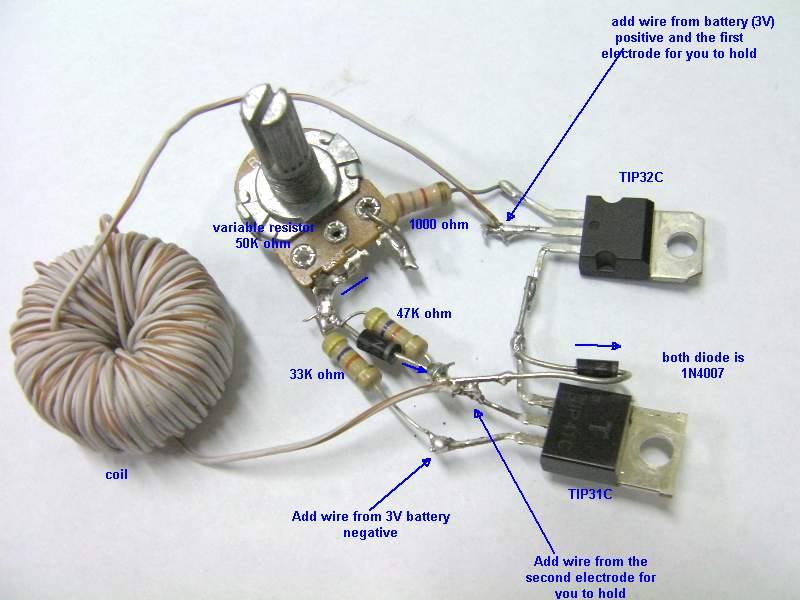 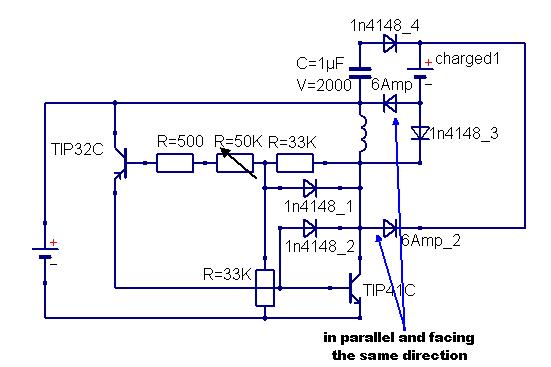 |
|
|
|
Post by Sucahyo on Apr 1, 2017 18:26:39 GMT 7
On the article here - www.thetruthdenied.com/news/2014/03/12/radiant-a-suppressed-fast-battery-charger/ - you show the wikipedia page regarding Flyback Diode. That page describes how 300v negative spikes are seen in a 24v circuit from a collapsing magnetic field of inductor. On the scope shot on the wiki page the negative spike is below 0v, ie, negative voltage. You say the spike on the scope shot you posted is mainly positive voltage, with just a small negative (below zero volts) spike. This is different from the wikipedia example which is mainly negative. I have heard Rick Freidrich say that different triggering on dc pulsed motors can create different characteristics of positive/negative spikes. So the hall effect trigger method gives more positive spikes, as does the opto trigger, while using a trigger coil gives a more negative spike, and a reed switch is also more negative. I do not have a scope to check the wave form of my circuits. But from what you say I believe the stingo spike is mainly positive spike - still radiant - but not negative. I believe positive radiant is compatible with regular charging (wall charging) of lead acid batteries, but negative spike will result in a 'dipole' battery, or problems trying to charge from the wall in future. As stingo is not negative spike do we really need the special diode arrangement? Have you used stingo to charge lead acid batts without these diodes? This can be confusing topic I am not sure if Rick use the same perspective. In that article positive is relative to the charged battery polarity. But rick seems to talk about the radiant polarity. Lets first assume that positive electricity is different from positive radiant. To make it simple lets use term female and male. Male effect is deteriorating, decomposing, accelerate chemical reaction, increase freezing point, loosen chemical bond. Female effect is stabilizing, decelerate chemical reaction, reduce freezing point, tighten chemical bond. This is my conclusion observing the effect of cemenite, orgonite, clouds buster to ice, motorcycle engine power, gas stove, weather and plant. Most thing have male and female polarity. Positive of battery is male. Negative of battery is female. The positive output of stingo may be male, the negative may be female. But this is not certain. Because the energy may flow different way. It can only flow along the wire if the wire is insulated. I think this is the reason for Tesla silk wire. But I believe PVC insulated copper wire is a good substitude. But, the overall energy of current stingo should be female. The diode next to the transistor bellow is the one that change the energy to female. If we take out the diode, then stingo will behave more male. I know this from people reaction when using stingo as health device. Without the diode long use may result in discomfort. With the diode even crying baby can sleep. The effect of male and female to battery is confusing. But I don't notice the difference between stingo with and without that diode in term of battery life. But male and female will certainly influence battery charging. Because sometime when I experiment with cemenite in engine power booster test, the motorcycle battery sometimes do not get charged. the charger polarity placement is very important. So I try to not make the wire cross to each other. We can find out the polarity of stingo if we put stingo in water and then freeze it. We can just decide from the ice. transparent is female. foggy/white ice is male. I never did this though |
|


 .
.
